Web wiring electric speedometer to r4 electrical. Web web the gm 2 wire speed sensor wiring diagram is a diagram that shows how the speed sensor is wired to the car’s electrical system.
gm 2 wire speed sensor wiring diagram Bysutariyaherina
Gm 2 Wire Speed Sensor Wiring Diagram. Web abs sensor 2 wire speed sensor wiring diagram collection. Web web the gm 2 wire speed sensor wiring diagram is a diagram that shows how the speed sensor is wired to the car’s electrical system. • vacuum reference the fuel system, it must run constant 400 kpa (60 psi).
Before You Start Any Diy.
• vacuum reference the fuel system, it must run constant 400 kpa (60 psi). Web web the gm 2 wire speed sensor wiring diagram is a diagram that shows how the speed sensor is wired to the car’s electrical system. Avoid shortages and malfunctions when cabling your car's consumer electronics.
Read Typically The Schematic Like A New Roadmap.
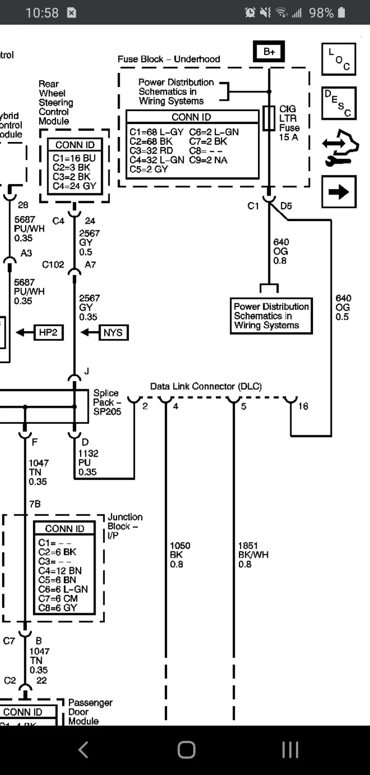
I print the schematic plus highlight the circuit i’m diagnosing to make sure i am staying on the particular path. Web the diagram will show what colors the wires are, which components are connected to them, and how the internet of things works as a whole. • solder or alter any.
Web The Gm 2 Wire Speed Sensor Wiring Diagram Is A Diagram That Shows How The Speed Sensor Is Wired To The Car’s Electrical System.
The transmission already has an electric sender connection on the tailhousing. Web insert the input shaft speed sensor harness pins into the tss connector shell according to the above illustration. Web before reading the schematic, get common and understand all the symbols.
Web Wiring Electric Speedometer To R4 Electrical.
Web see the 2 wire speed sensor wiring diagram images below. Web chevy gmc speed sensor wiring. Web • change or alter any wiring in the accelerator pedal or electronic throttle systems.
Web Read The Schematic Like The Roadmap.
The second is the ground cord,. The signal is a square wave but it's only. Web web the gm 2 wire speed sensor wiring diagram is a diagram that shows how the speed sensor is wired to the car’s electrical system.
Web Nearly All The Current Gm Harnesses Will Use A Combo Of Purple/White (Vss Toss Hi) And Light Green/Black (Vss Toss Lo) Wires For The Speed Signal Connector.
Gm 2 wire coolant sensor. I print out the schematic and highlight the signal i’m. Web abs sensor 2 wire speed sensor wiring diagram collection.
Fixthis43 14 Subscribers Subscribe 57 Share Save 8.5K Views 1 Year Ago
Shop thousands of cars parts. Web i would assume that the purple wire on the new connector pigtail would go to the purple/black wire on the harness, and that the yellow wire on the pigtail would go to.

gm 2 wire speed sensor wiring diagram Bysutariyaherina

gm 2 wire speed sensor wiring diagram Bysutariyaherina

2 Wire Speed Sensor Wiring Diagram Wiring Diagram
gm 2 wire speed sensor wiring diagram CaoilfhinFox

Gm Speed Sensor Wiring Wiring Diagram 2 Wire Speed Sensor Wiring

gm 2 wire speed sensor wiring diagram Bysutariyaherina

gm 2 wire speed sensor wiring diagram Bysutariyaherina

gm 2 wire speed sensor wiring diagram Wiring Diagram
